
LANCIA FLAMINIA... The Ground-up Restoration of Three Classics: The full story (35 minute read)
For SUMMARY Article (5 minute read), click HERE
CHAPTER 1
Introduction
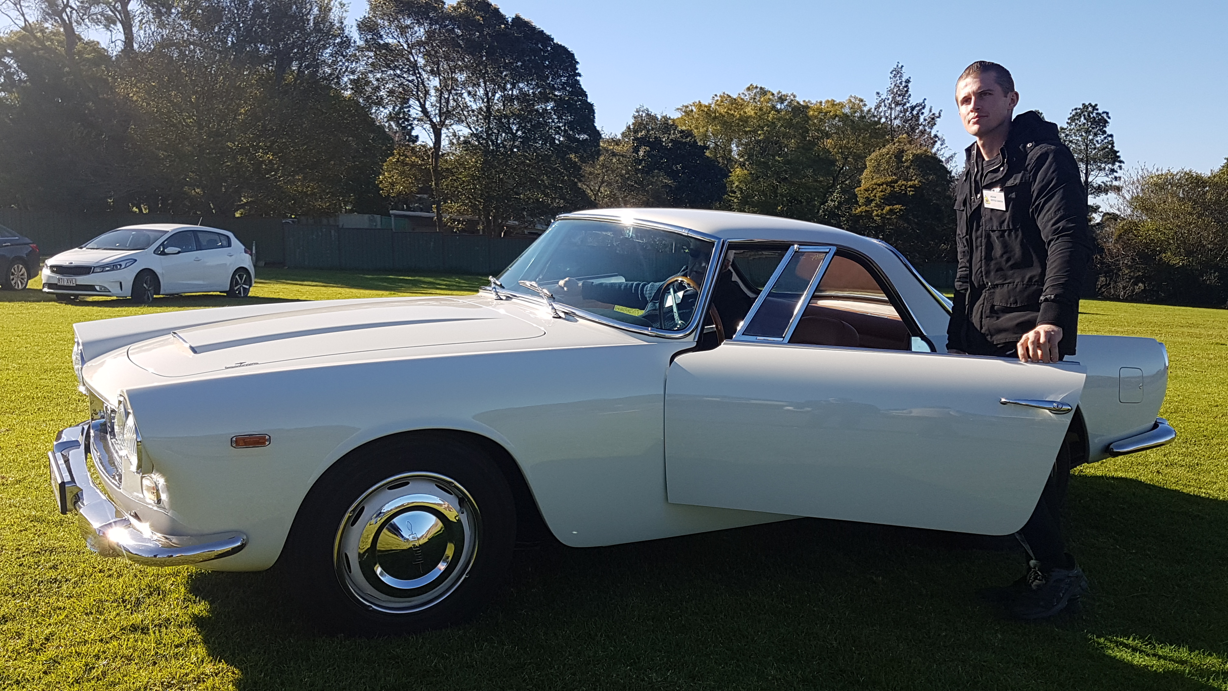
This project involved three Touring-bodied Lancia Flaminias, (two GT’s and a Convertible) that were saved from extinction and preserved by two very passionate Lancia enthusiasts for future generations. Following an extensive 5-year restoration project, the first of these is now registered (Photo 1), the second has been painted and undergoing final assembly, and the third car, (a very rare convertible) is currently being painted.
Automotive Craftsmen were commissioned in 2015, to restore these three classics for two different owners.
History of the Touring bodied Lancia Flaminia
The Flaminia was previewed at the 1958 Turin Motor show. Turin was the birthplace of many post-war industrial enterprises and the proud home of many of the great design houses of the period.
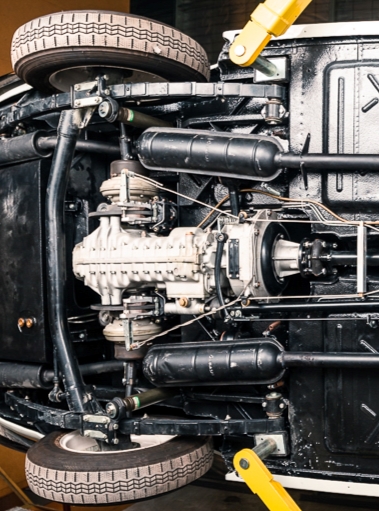
The Flaminia GT and Convertible were built between 1958 and 1965 by Carrosserie Touring of Milan and used Touring’s patented Superleggera construction method. This technique produced a lightweight vehicle and comprised a steel platform chassis with a system of small diameter steel tubes to form a skeleton, which was then clothed in a lightweight aluminium body. – (Photo 2).

These Lancia’s were very advanced for their time, and the Superleggera construction method was one of many innovations on this late fifties design. They were also one of the first to use 4-wheel servo-assisted Dunlop disc brakes, a rear mounted transaxle incorporating the clutch, and De Dion rear suspension with inboard discs. The Flaminia was the first Lancia to change from the Sliding Pillar front suspension that Lancia had used since 1921, and instead incorporated unequal length wishbones and coil-over shocker units which greatly improved the handling characteristics of the car.
The combination of the rear mounted transaxle, inboard discs and the De Dion rear axle made for a near 50/50 weight distribution which made it one of the better handling cars of the era.
As was the practice in the period, Lancia supplied the platform chassis (as shown in the detailed sketch from the original parts book – (Photo 3), from their works in Turin, to various carrosserie who designed and produced their own bodies. Apart from the sedan chassis (with the longest wheelbase) the Flaminia chassis was also available in two shorter wheelbases as supplied to Pinninfarina, Touring and Zagato.
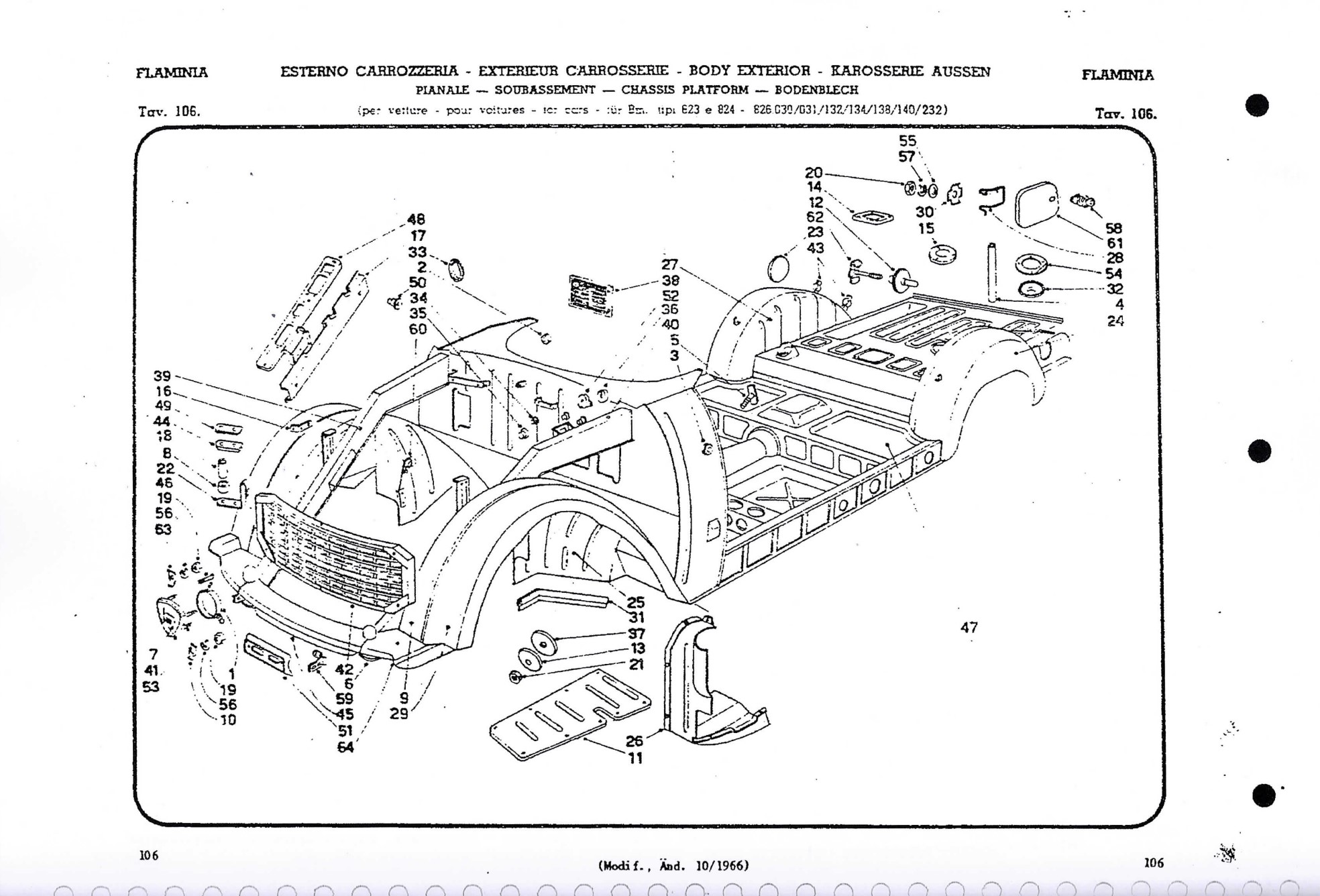
Note --- Almost all early Flaminias left the factory in L H drive. Later RH drive was introduced in limited numbers. The factory supplied the conversion components for those wishing to do their own RH conversion.
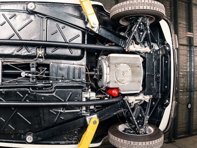
The platform chassis were sent to Touring mounted on a frame with castor wheels but without engine transmission and suspension. Touring would then hand build the bodies and fit all interior trim and send the painted bodies back to Lancia for final fitting of the suspension and driveline. (Photo 4).

There is a front subframe attached to the steel platform chassis at 6 points with rubber mountings
(Photos 5 & 6) and carries the engine and front suspension loads, steering, radiator & battery. The subframe is a critical part of the Superleggera design philosophy, as it stiffens the entire front of the car, and results in a very light but strong chassis unit, which enables the use of a very lightweight body shell.
.jpg)
This chassis design was common to all versions of the Flaminia including the Pinninfarina four door sedan and coupe, as well as the lightweight Touring and Zagato bodied cars. Using a common chassis with three different wheelbases allowed Lancia to amortise the development costs over a large range of body styles.
It should be remembered that these are cars were hand-built by artisans, and in 1961 you could buy three E-type Jaguars for the price of one Flaminia.
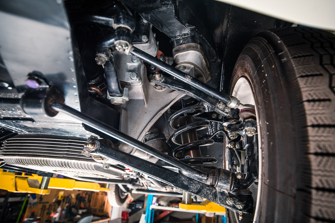
The front suspension assembly consists of two aluminium castings bolted to the main subframe, which are a triumph of classic foundry work, both in design and manufacture, and were way ahead of their time. These castings are designed to accommodate the wishbones, coil/spring units and worm and roller steering assembly. – (Photos 7 & 8).
.jpg)
The rear suspension is also a triumph of fifties automotive design incorporating a De Dion axle and semi-elliptic leaf springs. (Photo 9). The De Dion rear end reduces the unsprung weight of the vehicle as the transaxle is attached to the chassis, and unlike most fully independent suspension systems, there are no camber changes as the suspension moves through its range of travel.
The classic nature of these cars slipped from view at the onset of the seventies and were not appreciated. They were overshadowed by other marques with improvements such as Air conditioning, Variable-ratio power steering, Multi-link suspension, and fuel injection.
The revival started in the late seventies/early eighties when the classic designs of the fifties once again became appreciated.
The Lancia sales literature from the era contained a quote ---- “For those who know how special these cars are – you will be the one who buys it “
Brief history of 3 cars in this project
The first of three to be completed and registered, chassis # 824.00 *1202, was purchased by the current owner, Keith Schafferius in 2014. Keith’s car is a 1959 Series 1 car with the 2.5 Ltr. V6 with a single downdraft twin throat Solex Carburettor. There were a total of 796 Series 1 cars produced.
This car was originally imported from California in 2010 by a Lancia enthusiast in Melbourne with the intention of restoring it, but after two years decided to sell the it. The car was purchased and brought to Queensland by well-respected Lancia enthusiast the late Bob Anderson.
Bob then stripped the car in preparation for a total restoration. Due to health problems Bob then sold the car to Keith Schafferius in 2014. When Keith purchased the car, the aluminium body was still attached to the tubular frame, but the rest had been completely disassembled and was packed into boxes. – (Photo 10 - coming soon).
The other two cars (one GT and a convertible) are owned by well-known Lancia collector and Past President of the Lancia Club since 2006, Paul Doumany. Paul’s GT is a 1962 Series 2 car chassis # 824.10*3813 with very low mileage and a 2.5Ltr. V6, fitted with triple dual throat down draft Webers. There were 682 Series 2 cars produced.
Paul purchased the GT in England (UK Reg. MJK 11) in 2006 from Ken Buckley (father of well-known motoring journalist Martin Buckley), with the intention of garaging the car in the UK and using it on his trips to Europe.
The car had been imported into the UK early in its life in the mid-sixties and converted to RH drive using the factory supplied conversion kit. The major components of the kit being the steering and pedal box assemblies.
Paul subsequently decided he was not using the car enough in Europe and imported the car to Australia in 2012 and started planning a full restoration. During the restoration the car has been converted back to L H drive, to achieve full originality.
Paul’s convertible is a 1965 Series 3 car chassis # 826.134*1077, fitted with a 2.8 lt. V6, also with triple dual throat down draft Webers. The increase in capacity was achieved by enlarging the bore, while the stroke remained the same. There were only 180 convertibles made in this final form.
Paul purchased this car in 2007, from a well-known Sydney Lancia collector who had imported the car from the US in 2003. The chassis had a very serious corrosion problem after being abandoned in a field in Idaho and left to rot. There was a waterline halfway up the doors (and engine), and being a convertible, had repeatedly filled up with snow over several years.
Paul brought the car to Brisbane in 2007, and after a thorough evaluation decided it was too big to start at that stage, and put it aside to focus on a couple of other projects on the go at the time.
During discussions with respected Sydney motor engineer the late Don Wright which started in 2007, Don later said he was prepared to have a look at the engine to try and save it. Don convinced Paul to tackle the impossible – Rebuild an aluminium engine with steel liners that was seized and had sat idle (in the snow) for so many years.
Paul was highly motivated to save the original engine and have a matching numbers car, even though he had another identical engine from the same period from another Flaminia
Remarkably the engine was saved, and the total rebuild and bench testing were completed in just eight months. This was the catalyst for Paul to commence the full restoration of this very rare car
Paul has often commented that if the car had not been a convertible of such rarity, he would never have attempted the restoration, as the chassis and body were so badly corroded.
CHAPTER 2
The restoration project begins
Automotive Craftsmen commenced the restoration of these three classics in May 2015
First task – Remove Aluminium body from chassis
The aluminium bodies on these cars are folded over the steel chassis edges, and this had to be un- wrapped with great care to avoid splitting the 60-year-old metal. (Photo 11).

Keith’s GT body had been removed at a previous restoration shop and the chassis had been sandblasted and powder coated when it arrived at our workshop.
Both of Paul’s cars had the aluminium bodies still on their chassis, so the first job was to remove the bodies so the chassis could be chemically stripped using a dipping process.
This was a major task, as the only tank in Australia large enough to dip the entire chassis unit was in Sydney. Chemical stripping gives the best result, as the dipping process removes all traces of rust, even in internal panels that are not visible. It also removes all sound-deadening material and all other accumulated gunk. (Photo 12 -- ready for dipping)

The metal is then treated with a neutralizing solution and a de-oxidising agent for protection. (photo 13 – after dipping process)

Chassis Restoration
Keith’s chassis was the least affected by corrosion as it had spent most of its life in the dry climate of California. However, there were several areas where new sections had to be fabricated and welded into place. (These are shown in Photos 14 to 17).


Once this work was completed this chassis was also sent to Sydney for the full stripping process.
Pauls GT chassis corrosion was more severe with approximately 20% needing replacement. Paul also wanted to return the GT to left hand drive to maintain originality as it left the factory. This involved detailed fabrication of the dash fascia panels for the instrument cluster and the glove box, grafting the structural support brace for the steering column back to the LH side of the under-dash frame, and filling/drilling all the firewall holes.
This car had also suffered previous accident damage to the right front guard and liner. The guard had been repaired but we had to manufacture a new inner liner. The bonnet opening frame also had suffered corrosion and had to be replaced, and a new spare tyre floor had to be fabricated
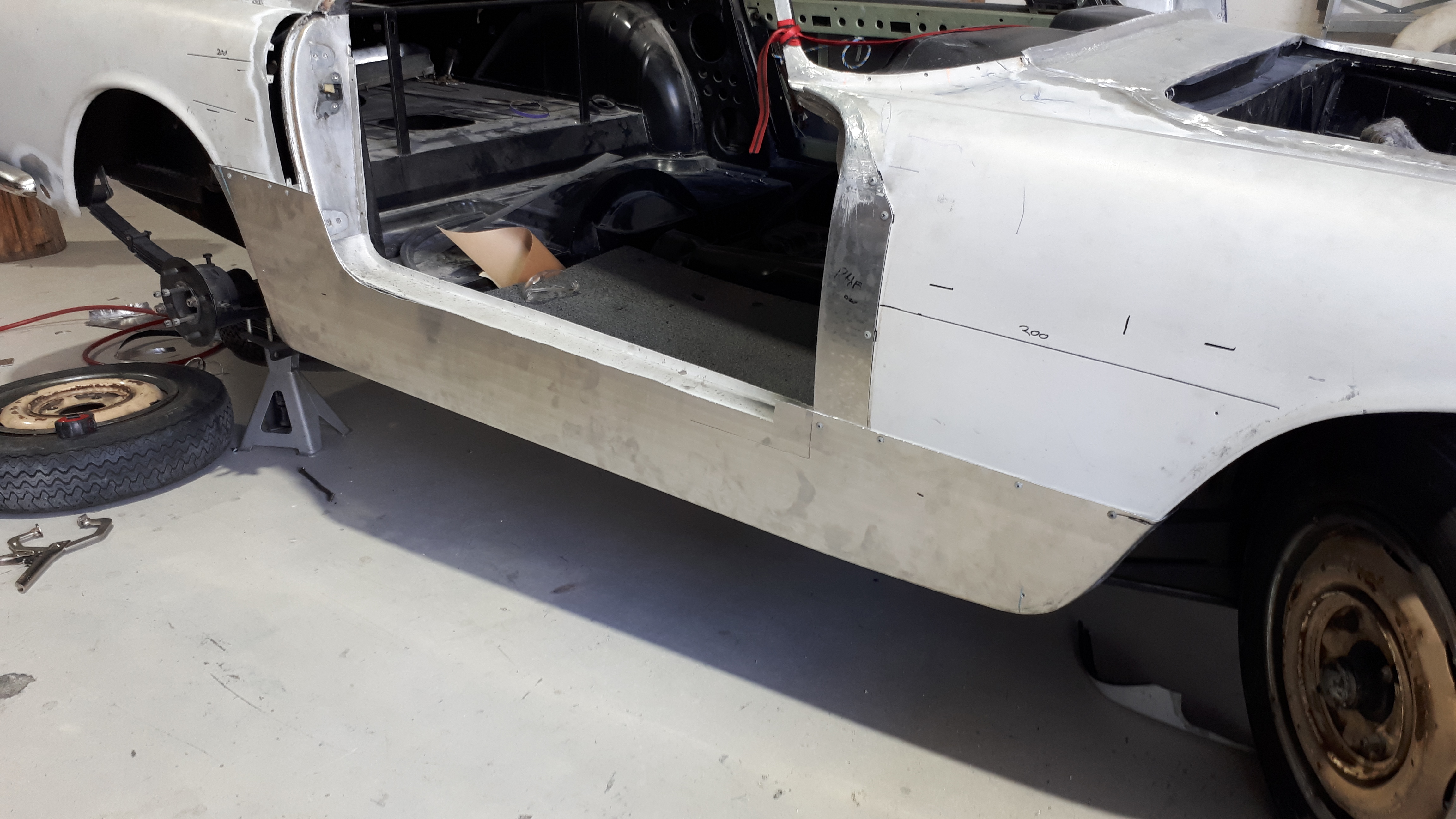
The sill panels on all three cars needed extensive re-building and the area around jacking points had serious corrosion so the opportunity was taken to strengthen these areas with an additional internal beam running the length of the sill.
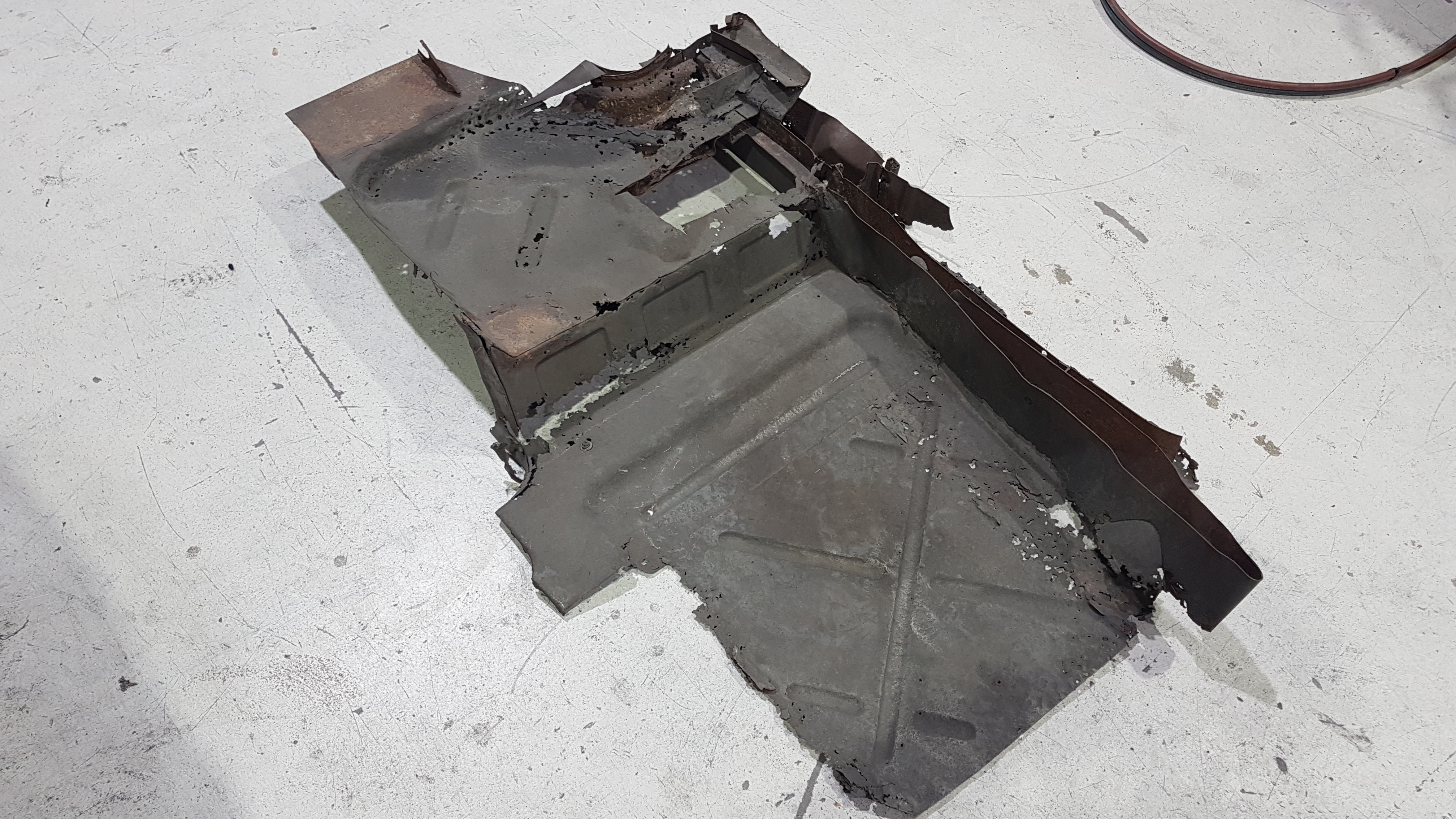
Paul’s convertible, that had spent many years sitting in a field, was so badly corroded that around 90% of the floor including the boot had to be replaced. New sections of the floor including the seat mounts were fabricated by hand with great care taken to exactly replicate the ribbing, -- (Photo 18).
.jpg)
The rust was so severe (Photo 19) that it was not just the sheet metal floor pan that had to be replaced, but even new seat mountings had to be re-manufactured – (Photo 20).

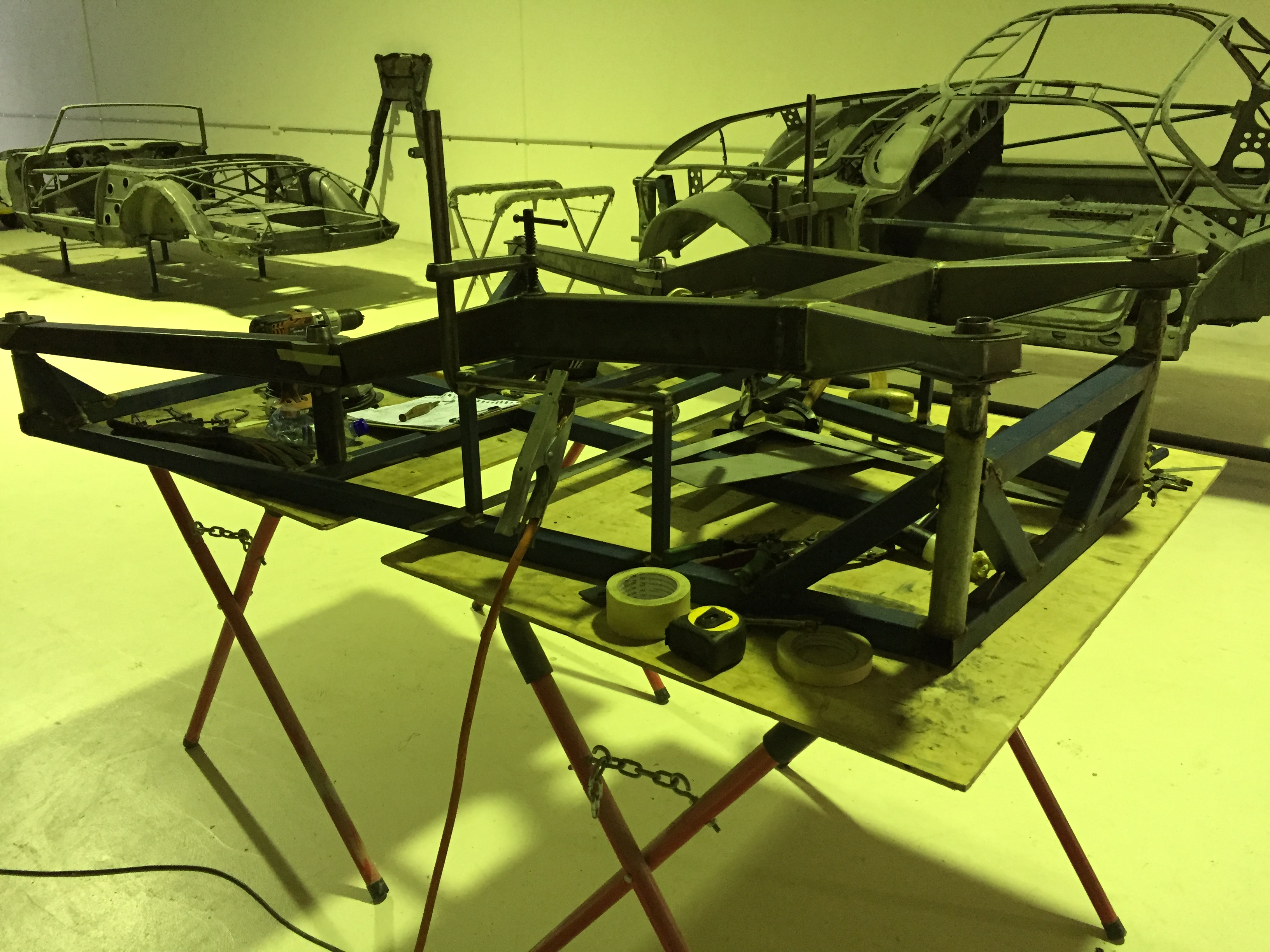
A major task was to fabricate new sub frames for all three vehicles as there was severe corrosion in all the subframes. (Photo 21).

As can be seen in (Photo 22), the subframe is a complex piece of kit, and the alignment of all mounting points is critical, particularly the suspension mounting points. The only parts of the old subframes that could be saved were the four engine mounting points, and four suspension mount crush tubes.

Using the best of the old subframes, accurate dimensions were taken, and all steel cut to size and the individual sections were welded together then placed in an assembly jig for final welding along with six new chassis mounting points we had to fabricate. Paul was able to supply an assembly jig he had from a previous project. (Photo 23)
Aluminium Body Restoration
Part of the Superleggera design philosophy is to fold or wrap the aluminium skin over the chassis edges and tubes to minimise weight. There are no bolt-on panels on these cars – (bolts and nuts are too heavy!)
The strength of the design is in the unitary construction which gives the chassis/body unit its inherent torsional rigidity and lightweight.
As part of their brief at the start of the project, Keith and Paul had a strong desire to keep as much as possible of the original cars intact, particularly the aluminium body.
While Keith’s car had the least rust in the chassis, ironically it also had the most panel damage in the aluminium body from previous repairs, that had been poorly executed earlier in its life.
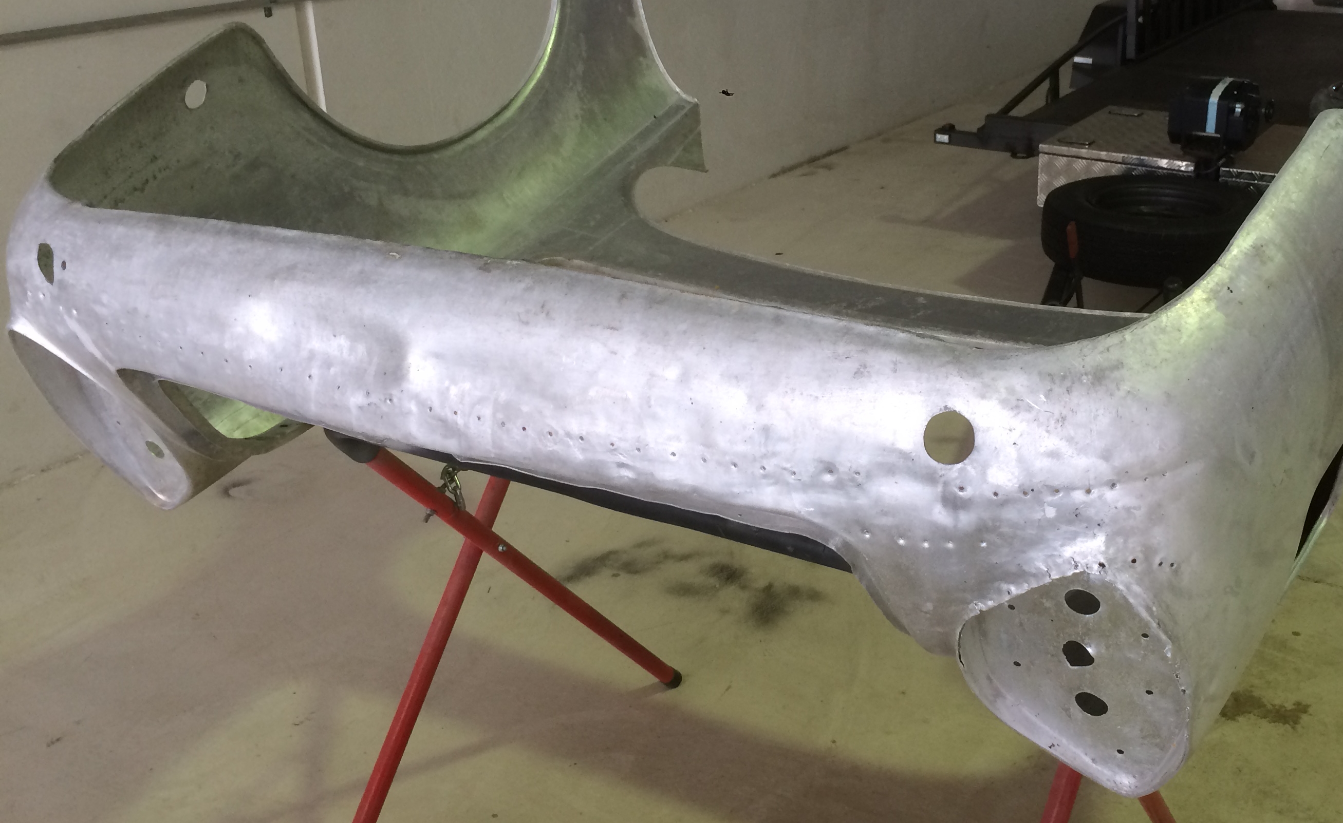
An example of this is the rear beaver panel (under the rear bumper), where over 100 self-tapping screws had been inserted by a previous repairer, to try and pull out the damaged area. – (Photo 24) Each of these holes had to be carefully welded to maintain the original panel intact. --- Easy job on fresh aluminium – but quite a challenge on 60-year-old aluminium!!!
The greatest challenge when working with 60-year-old aluminium, is the difficulty in re-crimping edges of the aluminium skin over the steel frame, after the frame and body have been restored. Even with the careful annealing process utilised, un-folding these edges from the frame causes micro stress fractures in the aluminium, and then further serious cracking when it comes time to refit the aluminium skin back to the frame.
The annealing process for 60 year old aluminium is an art in itself, as it important to know which part of the flame to use to avoid overheating, and just how much carbon deposit is required on the very small sample area you are about to unfold.
There were some sections too badly damaged to repair, so new sections were fabricated e.g. – taillight area (Photo 25) and the edges of the front and rear clips.

This required some serious solutions and significantly increased the labour content. It required a strip of the original aluminium skin (approx. 50mm wide) be trimmed from the circumference of the panel and new aluminium be welded on – (Photo 26) .This then gave fresh material to be re-folded over the steel frame.
However, welding this new aluminium to the existing skin provided a major challenge due to the breakdown in the chemical structure of the old aluminium. Over time as the metal is exposed to oxygen and the environment, its chemical structure is broken down.
The white blotches seen on aluminium is the start of corrosion etching itself into the metal and is one of the many factors that increase the difficulty of restoring old aluminium bodies.
Considerable research was required to determine the best welding method. Most impactful part of the research was finding the technique for the cleaning and preparation process of the old aluminium. Several different chemical treatments were tried as well as rotary wire brushing, before the final decision was made.
A combination of abrasive sanding with an orbital sander to remove the corroded aluminium from the surface, and the rotary wire brush to clean out the contaminates that remained in the micro-pitting.
When these vehicles were built around 60 years ago there was not enough thought given to the potential for corrosion where the aluminium and steel meet.
The first problem is there was no cathodic protection where the aluminium skins were folded over the steel frame.
The second major problem with the superleggera construction method, was the use of felt and/or hessian between the steel tubes and the aluminium skin to prevent squeaking/vibration, which gave an opportunity for water to saturate the felt or hessian to start the corrosion.
When restoring these classics, future corrosion prevention is an important consideration, as the combination of steel frame and aluminium skin can cause an electrolytic reaction. To prevent this happening, the metal frame was sandblasted and primed with a high-grade epoxy primer. The edge of the steel frame is then covered with a layer of high quality anodised aluminium tape, and the aluminium skin is then re-crimped over the metal frame. Once all the skins were re-crimped, fish oil was then sprayed around all seams.
New aluminium door skins were fabricated for all three cars, and while the door skin appears to be a relatively simple shape the difficulty factor increased considerably along the top edge of the skin.
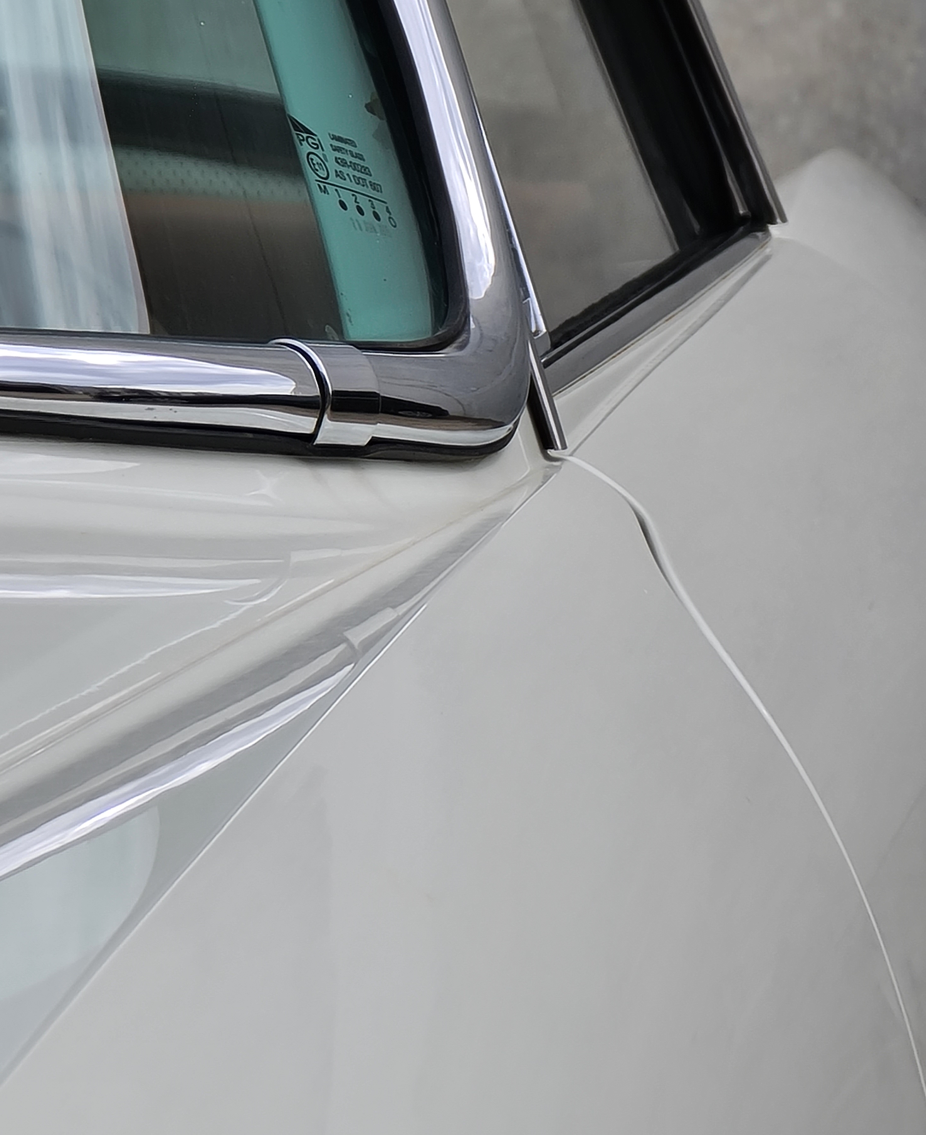
There are several converging and diverging style lines that form an important part of the overall design philosophy of these classic, and they run from the front headlight right through to the rear taillight. (Photo 27). These lines running through the upper section of the door, do not lose their unique trajectory as they continue to taper from front to rear, and delineate the lower body from the slim roofline which is the defining element that makes this design a classic fifties icon.
At the front upper corner of the door, there are 4 folds within 40 mm, three of which converge to blend into one by the time they reach the rear edge of the door. This is an excellent example of the skill level required to produce a panel with such intricate detail. The biggest challenge in re-manufacturing these door skins, is the very tight changes of direction which must align with the lines in the front and rear clips. (Photo 28 - coming soon) shows a trial piece made first to perfect the technique, before the full one-piece aluminium door skins were fabricated
The inner door frames on these cars are steel and were all badly corroded to the point where the only part that was able to be salvaged on five of the doors were the hinges and the upper section of the frames. A completely new RH door had to be manufactured for Paul’s GT, as the steel inner skin had extensive rust and was beyond repair. The cast hinges were able to be re-used but there is a complex hinge mount brace inside the door frame that had to be re-manufactured.
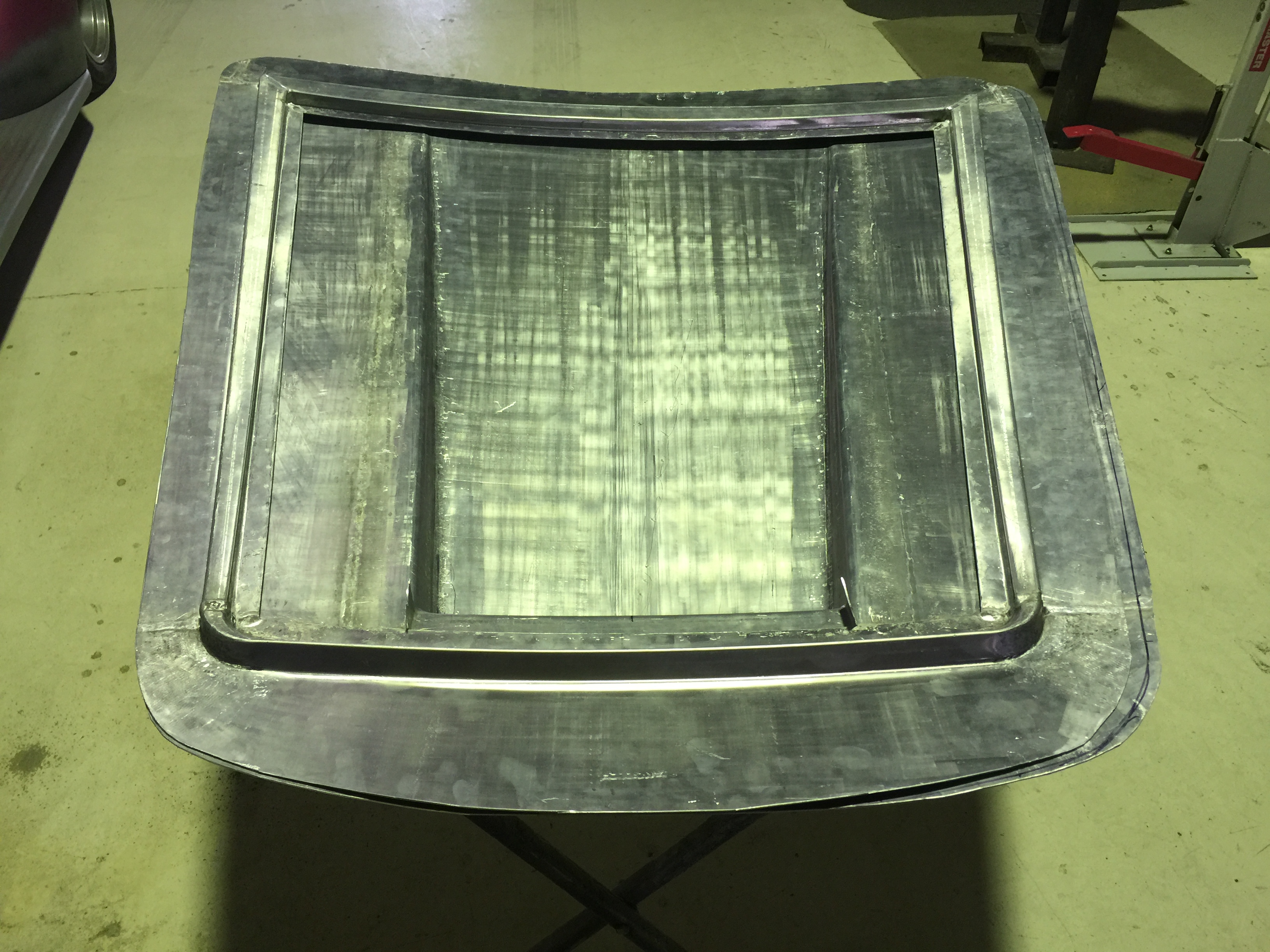
A new aluminium bonnet including inner skin was re-manufactured for Keith’s car. (Photos 29 & 30).

CHAPTER 3
Upholstery
Tony Cairns produced the Concours standard trimming in high quality leather for the interior of this beautiful car. The seat bases were fully re-built with new springs and new foam was shaped. (Photo 31).

Tony was for many years a judge at the Summernats. He has been responsible for many show winning automotive interiors. Tony now does most of his work on aircraft interiors
Painting
Brent Doring did the paintwork on Keith’s car and is also doing both cars for Paul. He has done Paul's work on several Lancia’s in the past.
Brent did his early training as a high-quality vehicle painter and then moved into specialist painting of luxury super yachts, before returning to vehicle restoration.
Brent’s philosophy follows classic painting techniques. Starting from a sound base of epoxy primer, expertly sealed seams and carefully applied building agents, Brent takes the time necessary to achieve a perfect result.
CHAPTER 4
Final Assembly of # 824.00 *1202
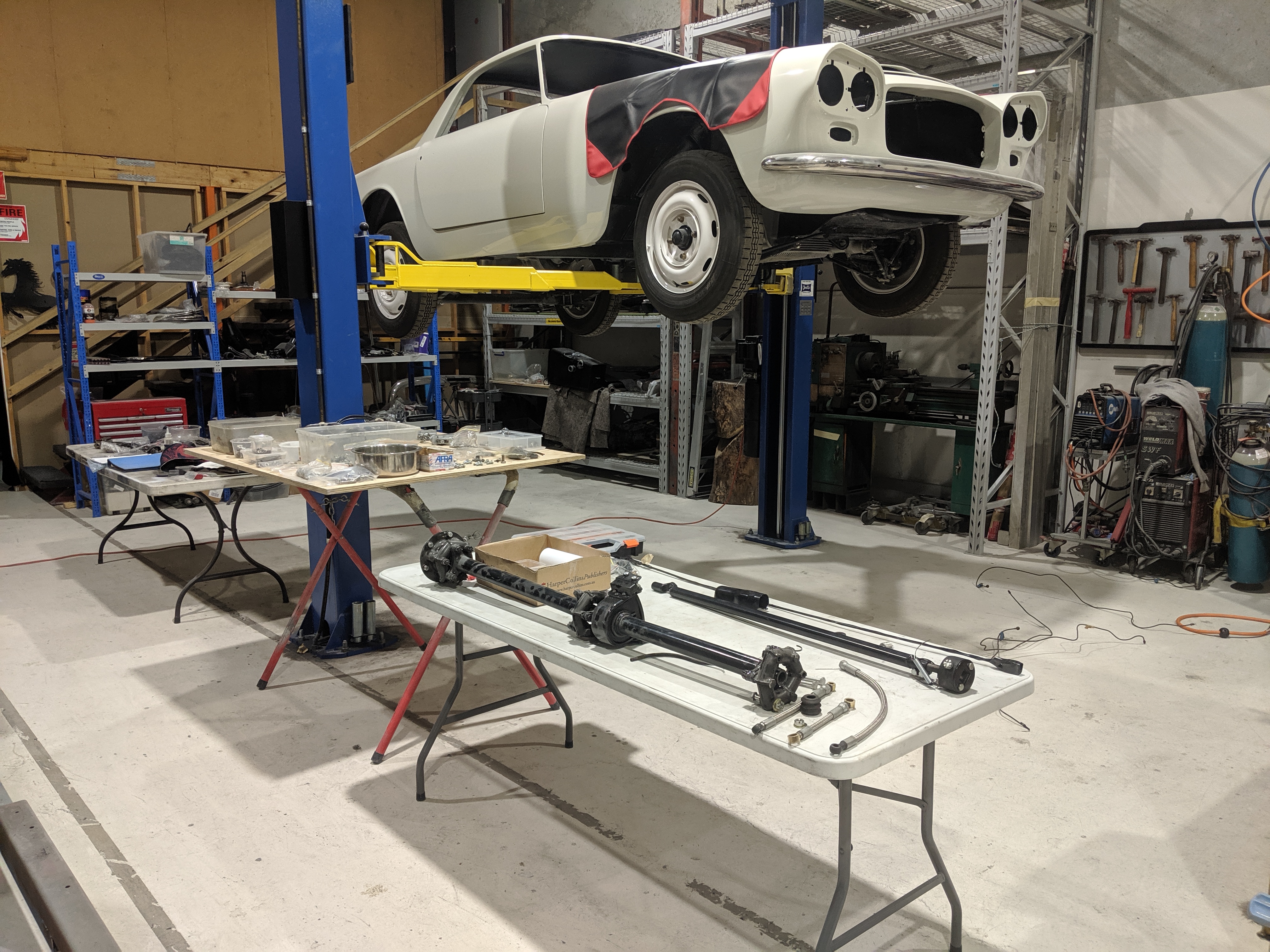
The original plan was for Keith to do all assembly work in his workshop at Acacia Ridge, but after a detailed examination of all the boxes of bits it was decided that Automotive Craftsmen should complete the assembly. — (Photos 32 & 33).
.jpg)
We soon realised our greatest challenge was the lack of correct reference material – we had a workshop manual and a parts book but these were for the Pinninfarina bodied Flaminias, and while the chassis and running gear are essentially the same, we found things were quite different in areas such as fuel and brake systems. – Many details were very sketchy, and a great deal of detail was missing.
As Keith’s car was an early Series 1, there were quite a few changes made as production progressed and a lot of information in the manual was for later models. It was very hard to find info on the early cars.
This led to some challenges when it came to the manufacture of new brake lines. Being an early car, it was fitted with the Simplex braking system, whereas later Series 1 cars were fitted with the Duplex fail-safe system. To compound the problem there was a box of brake line fittings (distribution blocks etc) with enough for 3 cars as the previous owner had collected additional items as they became available. There was also an assortment of brake lines, but these had several different flared ends some of which did not match up with the fittings. We had to be careful to select the right flare for the correct thread pitch and fitting.
The fuel system also proved challenging as this was completely different to the system shown in the manual. These early cars were fitted with a mechanical pump, which necessitated two long sets of lines as there was a main tank plus a reserve. As these mechanical systems are unreliable a decision was taken to fit an electric pump as on later Series 1 Touring Flaminias.
We endeavored to complete as much of the work in-house as possible to control the quality. We set up our own small zinc plating station, so all small parts could be plated in-house. History is littered with stories of the plater losing bolts, or you send 27 bolts and nuts to the plater and get a bumper bar back!!!
One of the many boxes of parts to be sorted was a very large plastic box full of bolts, nuts and washers both in metric and imperial. The first task was to isolate the original Lancia bolts which have the Lancia logo stamped in the head, from the myriad of Fiat and other bolts of all shapes and sizes.
As the owners were keen to retain the originality of these cars, right down to the correct bolts and nuts, our task was to restore damaged heads and threads to save as many bolts as possible. Damaged heads were built up with weld and then machined. We were able to source a few of the bolts we were missing from Europe, and for the unobtainium, we machined down some of the larger spare bolts to a smaller size and therefore retain the correctly marked heads. In addition to missing bolts and nuts, there were also many brackets etc missing that had to be fabricated from scratch.
The handbrake mechanism was another case of lack of any documentation for the early Series 1 cars. There is a complex series of levers and pulleys to activate the handbrake, and the challenge was to set this up in the correct sequence to apply the correct pressure to the brake disc. We also had to fabricate a floor pan brace to prevent the tunnel brackets from flexing when the hand brake was applied. This system was refined on the Series 2 cars.
The lighting system had to be converted to comply with Australian Design Rules before the vehicle could be registered. The European system from the period used a twin filament bulb in the small rectangular light fitting below the twin headlights. This twin filament bulb operated the park light and indicator. This did not comply with ADR’s and the park light had to be moved to the outer of the twin headlights which contained the low beam. The indicator remained in the small rectangular fitting below the twin headlights, however coloured filament bulbs were unavailable, so a standard bulb was treated with a dye to tint the glass bulb.
The strut mechanisms for the bonnet and boot needed some attention, and these were completely stripped, zinc plated and re-assembled. Achieving the correct tension on the mechanism required a serious level of patience to find the correct wave washer combination to allow the mechanism to function efficiently with the load of the bonnet and boot applied.
The horn was another challenge, as the contact switch that activated the horn was damaged beyond repair, and a replacement could not be found. This called for some creative ingenuity and a generic automotive door switch was modified and mounted on the steering column. The brass contact ring was then repaired and mounted to the body under the dash surrounding the steering column, so the modified spring-loaded door switch contacted the brass ring through 360 degrees of motion. As there was a non-conductive flexible coupling fitted to the steering column, a short earth cable was then fabricated to connect the circuit between the steering box and the column.
The generator that came with the car did not have a pulley. Keith was able to source one that had the correct V- groove profile, but the cooling fins scraped on the body when the belt was tensioned. We were able to set it up in the lathe and machine this down to overcome the problem. A tensioner mount also had to be fabricated to rotate the generator to achieve a satisfactory tension to the belt.
The water pump had previously been re-conditioned before the car came to us, and when we first ran the engine there was a severe scaping noise coming from the pump. On stripping the pump, we found that the incorrect bearings had been used. They were 2mm narrower than the originals and the spacer between the bearings was now 4mm too short and allowed the shaft/impeller/pulley assembly to float, and the pulley was scraping on the water pump housing. To overcome this problem, we machined a new spacer 4mm longer and re-built the pump.
As mentioned earlier these cars have a rear mounted transaxle which incorporates the clutch. The tail-shaft is attached directly to the flywheel and is therefore spinning at engine speed, as opposed to the convention at the time of a front mounted engine clutch and gearbox, then tail shaft to a rear mounted differential.
This requires the whole driveline assembly to be very well balanced to avoid any unnecessary vibration. The transaxle including the clutch had been rebuilt before the vehicle came to us, and the tail-shaft assembly had also been rebuilt and balanced. When the final assembly of the car was completed, we took it out for the first test drive, and there was serious driveline vibration.
We then set about resolving what would prove to be one of the most challenging episodes of the whole assembly phase of this restoration. While the engine was running on the hoist, we also noticed the Harmonic Balancer/Vibration Dampener on the front of the crankshaft was not running true. A decision was taken to check the balance of all components in the drive train so the problem could be resolved as quickly and efficiently as possible.
The tail shaft assembly was removed first, the clutch was then removed from the transaxle, and the harmonic balancer removed from the front of the crankshaft, so that all components could be checked and balanced correctly.
The main drive shaft is a complex two-piece unit with a rotorflex coupling joining the two halves, and another at each end to attach to the engine and transaxle. There is a centre support bearing that had been previously reconditioned, and the driveshaft is assembled around this centre support bearing, which is contained within a rubber vibration dampener and attached to the chassis (as shown in Photo 34).
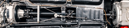
After a detailed inspection of all components, we noticed that when the tail-shaft had been re assembled, the factory markings on each coupling yoke had not been properly aligned on assembly, and this was one factor contributing to the severe vibration. The coupling bolts were also of varying lengths, so these were all machined to be equal weight.
We also found that when the clutch assembly had been reconditioned, it had been re-assembled using different length bolts, which although may seem insignificant, was another factor contributing to the vibration.
Balancing the tail-shaft as an assembly proved challenging but we finally found a machine that could balance it as a complete assembly at Hardy Spicer in Brisbane.
On close inspection of the harmonic balancer we found one of the O-rings had been pinched on assembly, and this was causing the run-out and adding to the total vibration load, so we had to strip the unit and source new O-rings and then reassemble the unit.
A combination of all these small fixes, resulted in removing the driveline vibration. The final task was to organise compliance and registration.
The End result
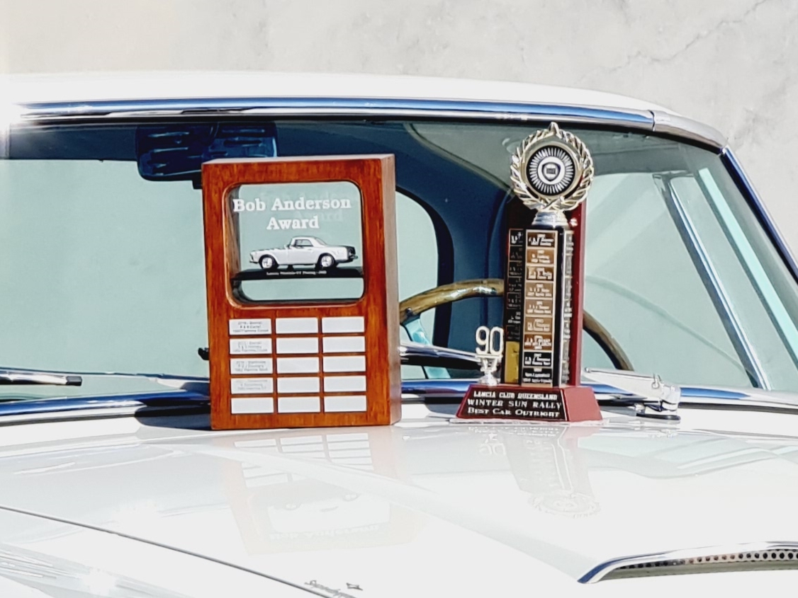
After 5 years of overcoming challenges by the team at Automotive Craftsmen, and commitment and dedication by the owner, the car was presented at the Lancia Club Annual Rally in Toowoomba in July 2021, and was awarded the trophy for the Best Car Outright and fittingly the Bob Anderson Trophy for the best Flaminia of the Rally. (Photo 35).
Have a question?
Send us a message using the contact form below or just give us a call.

